English

HV DC - dielectric strength test equipment

homepage > Products > HV Test - Dielectric strength > HV DC - dielectric strength test equipment
The test allows to verify the dielectric strength or the insulation of the cables or electrical products for which this test is required, at a voltage and for a time determined by the reference standards or by customer specifications, in the R&D phase or at the end of the production


SIF presents a new system for high voltage direct current dielectric strength tests. The system is aimed at both electrical cable manufacturers and other sectors where this type of test is required.


Innovation, safety and flexibility in the same system, all as standard


DC equipment has the advantage of using a low-power generator.
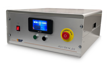
The compact dimensions of the equipment allow it to be used both in the laboratory and near the production lines, while considering all aspects of operator safety.

The equipment is completely digital, with a 4.3” HMI color graphic touch screen for selecting the test and operating modes and for periodic calibrations and complete with an automatic discharger to ensure maximum operator safety, all as standard.


MODELS

Features

iRDC15K14_DS
iRDC15K08_DS
iRDC15K02_6S_DS

Max. output voltage kV DC

15

15

15

Max. output current mA

14

8,3

2

Output voltage accuracy

±(2%+50V)

HV ramp setting

(0,25-0,5-1-2-5) kV/s

Timer

99 m 59 s

Short circuit current

Adjustable

Adjustable

Adjustable

Voltage supply

230 V 50Hz

Discharger at the end of the test

4 starting modes selection

4 testing modes selection

Automatic test cycle for 3-pole cables with or without connector


Contact for signaling external safety lights

External security input

Standards compliance

CEI EN IEC 61010-1, CEI EN 50191 

TESTING MODES

1. AUTOMATIC – automatic test

  • set: test voltage, test time, HV ramp speed, short circuit current
  • cycle: ramp up to the set voltage value, time start, down ramp when the time is over
  • fault (short circuit): in the event of a defect, the voltage value and the time reached are stored


2. MANUAL – manual test

  • manual voltage regulation


3. BD – Break Down

  • set: test voltage, test time, HV ramp speed, short circuit current, max. voltage
  • cycle: first ramp up, time starts at the voltage value, then second ramp up until maximum voltage, final time and ramp down
  • BD fault: in the event of a defect, the voltage value and the time reached are stored  


4. BDS – Break Down Steps

  • set: test voltage, test time, HV ramp speed, short circuit current, max. voltage to be reached and number of steps from 1 to 5 with automatic calculation of the voltage division according to the steps, time for each step
  • cycle: first ramp up, the time starts at the voltage value, then second ramp up until the calculated voltage value, repeats for the number of steps up to maximum voltage, final time and ramp down.
  • BDS fault: in the event of a defect, the voltage value and the time and step reached are stored


5. 6S – 6 Steps - ONLY FOR iRDC15K02_6S_DS MODEL  

  • set: test voltage, test time, HV ramp speed, short circuit current.
  • exclusions: continuity CON 1, continuity CON 2, continuity CON 3, CTO LV 2 vs 3, CTO HV 1 vs 2, CTO  HV 1 vs 3
  • cycle: continuity of 1, 2 and 3 conductors; check SHORT LV 2 vs 3, check SHORT HV 1 vs 2 ramp up, the time starts at the voltage value, ramp down at the end of the time, check SHORT HV 1 vs 3, ramp up, the time starts at the voltage value ,ramp down at the end of the time.
  • fault (short circuit): in the event of a defect, the voltage value and the time and step reached are stored

Discharger: HV closing at test start, earthing closing at test end, test disconnection at the end of discharge

STARTING MODES

1. Independent START and STOP button – pressing the START button activates the test and, if the test does not stop automatically, pressing the STOP button interrupts the test

2. START button and STOP button to be pressed together – the START and STOP buttons must be pressed and held down until the end of the test. When you release the buttons the test stops. 

3. Double external START button  – Connect the two START buttons in the connector. Both external START buttons must be pressed and held down until the end of the test. When the buttons are released, the test stops.

4. External pedal button – You plug the button into the connector. Pressing the pedal activates the test and, if the test does not stop automatically, pressing the STOP button interrupts the test.

Traditional analog equipment


Equipment features:


  1. Test voltage up to 15kV
  2. Test current up to 10mA
  3. Test parameter reading instruments
  4. Automatic detection and shut off circuit in case of short circuit
  5. Automatic tested cable discharge circuit in case of  short circuit or at the end of the test
  6. Timer for automatic test
  7. Operator panel with start and stop buttons, "testing" and "ok/no test" signals.
  8. Emergency button
  9. Predisposition for interlocking with test box safety
  10. Adequate high tension cable for cable connection